Monday, August 29, 2016

LM7001 FM Transmitter

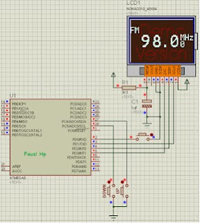
LM7001 FM Transmitter that will be created using Atmega8 controllers and use the Display Nokia 3310,
and the code is created using BASCOM-AVR. for FM oscillator using FET transistor 2SK192A.
The first and second buffer FM transmitter using transistor 2SC2026. Drivers using a transistor 2SC2053. 
Final use 2SC1947 Transistor.

LM7001 FM Transmitter

LM7001 and LM7000 have the same internal registers. so you can use LM7000 for this project. and incidentally we use LM7000 as Component testing. LM7000 is not so popular, the difference lies in the number of pins.

LM7001 FM Transmitter
LM7000 has 20 pins, and the LM7001 has a 16 pin


for a LM7000 or LM7001 simulation software we use Proteus. The following schematic controllers


Programming LM7000 or LM7001:
LM7000 / LM7001 is controlled using a protocol 3 wires. each Data, Clock (CL), and Chip Enable (CE). the figure below shows the timing Programming LM7000 / LM7001.

to begin programming the CE pin must be logic high, and then prepare Data. The next step is activated Clock (CL).

for the calculation of frequency using the following formula: 


Monday, August 22, 2016

How to Make a Digital Tone Control

DIGITAL TONE CONTROL has advantages compared to Analog Tone Controls. Analog Tone Control frequently encountered problems. the use of conventional Potensio will experience wear that will disturb Audio. balance Audio L and Audio R will have problems. DIGITAL TONE CONTROL has a more attractive appearance with LCD Display or Seven Segment.

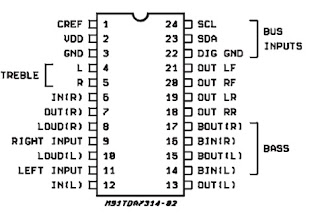
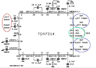
The main components to create a Digital Tone Control is IC TDA7314S. TDA7314S Digital controlled by the I2C protocol. Fewer external components are needed to make this DIGITAL TONE CONTROL. IC TDA7314S facilities Audio settings include Volume, Bass, Treble, Loudness Active, and balance. IC TDA7314S banyak diterapkan pada perangkat Audio Mobil.

How to Make a Digital Tone Control


How to Make a Digital Tone Control


How to Make a Digital Tone Control


as usual in any project that involves controlling, we use a microcontroller from Atmel company. Atmega8A we are very suitable to use for that purpose. we have yet to find a solution other than Atmega8 for small projects. we never had any information on the microcontroller cheaper than atmega8. Nuvoton offers 8051 microcontroller with additional peripherals, such as Atmel AVR. it will be considered.

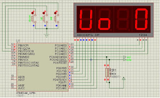
we want the Digital Tone Control has a compact design. to access using Rotary Encoder with a single button push on. push button on function to select the mode that will be accessed. such as volume, bass, treble, Loudnesss, and Balance.

seven segments we use to display the reason cheap, and widely available on the market.

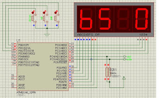
the image below in the volume mode:

How to Make a Digital Tone Control

the image below in the Bass mode:

How to Make a Digital Tone Control

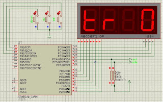
the image below in the treble mode:

How to Make a Digital Tone Control

continued.................

Sunday, August 21, 2016

How to Make a Digital Clock With Atmega8 Microcontroller

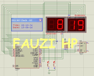
Time is so precious .... on this occasion I will give a tutorial how to make a digital clock using microcontroller Atmega8. Digital Clock is very simple. Atmega8A only consists of Microcontroller, RTC DS1307, and several supporting components. Digital clock can be set and added Alarm. Digital Clock is suitable mounted on the wall.

How to Make a Digital Clock With Atmega8 Microcontroller
Shematic Digital Clock Atmega8A

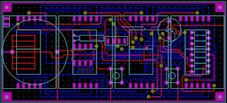
of the first plan is to be made with the right size with a field of seven segment as the primary display. the size of seven sections 1 "I think it is very appropriate, not too big and not too small. total size of seven segments are 10x4.5 cm. PCB size will follow the size 10x4.5 cm. very difficult to design a PCB with a size of 10x4.5 cm with a single layer PCB. therefore I had to use a Double Layer PCB.
below are the results of the PCB design

How to Make a Digital Clock With Atmega8 Microcontroller
PCB Digital Clock Atmega8A


How to Make a Digital Clock With Atmega8 Microcontroller

How to Make a Digital Clock With Atmega8 Microcontroller

How to Make a Digital Clock With Atmega8 Microcontroller


the following code digital clock Atmega 8A:

'jam digital
'atmega8a
'by fauzi hp

Config Timer0 = Timer , Prescale = 64

On Ovf0 Tim0_isr
Enable Timer0
Enable Interrupts

'buat PORTC & PORTD sbg output

Config Portc = Input
Config Portb = Output

Portc = &B11

Ddrd = &B10011111
Portd = &B01000000

'pengaturan kaki RTC, menyesuaikan kaki RTC dgn kaki Mikrokontroler

Config Sda = Portc.2
Config Scl = Portc.3

'alamat device RTC, setiap perangkat I2C mempunyai alamat device berbeda-beda

'kebetulan untuk IC Jam RTC alamatnya "&HD0" untuk operasi Write dan &HD1 untuk
'operasi Read
Const Ds1307w = &HD0
Const Ds1307r = &HD1

Config Clock = User


'variabel2 yg diperlukan

Dim Weekday As Byte
Dim Digit As Byte
Dim Satdetik As Byte
Dim Puldetik As Byte
Dim Satmin As Byte
Dim Pulmin As Byte
Dim Satjam As Byte
Dim Puljam As Byte
Dim M0 As Bit
Dim M1 As Bit , M2 As Bit , M3 As Bit , M4 As Bit
Dim Jam As Byte , Jams As Byte
Dim Menit As Byte , Menits As Byte
Dim Ctrbzr As Word
Dim Bzr As Bit
Dim Aljam As Byte , Almen As Byte
Dim Disp As Bit
Dim Satmintmr As Byte , Pulmintmr As Byte
Dim Satjamtmr As Byte , Puljamtmr As Byte
Dim Alrmjam As Byte , Alrmmin As Byte
Dim Aljamadr As Byte , Alminadr As Byte
Dim Kedip As Byte
Dim Kdp As Bit

Dim Satsuhu As Byte , Pulsuhu As Byte , Suhu As Byte

Dim Temp As Single
Dim Vadc As Word
Dim Tamp As Bit
Dim Dlytemp As Word
Dim Jamsuhu As Word
Dim Komsuh As Byte
Dim Satkom As Byte , Pulkom As Byte

Alminadr = 1

Aljamadr = 2

If Pinc.0 = 0 Then

   Time$ = "14:01:59"
   Date$ = "12-10-15"
End If

'aktifkan detik di RTC

I2cstart
I2cwbyte Ds1307w
I2cwbyte 7
I2cwbyte &B00010000
I2cstop

Readeeprom Aljam , Aljamadr

Readeeprom Almen , Alminadr

Do


Loop


End


Tim0_isr:

   'pemanggilan subrutin baca RTC
   Gosub Getdatetime
   'ambil nilai satuan & puluhan detik
   Satdetik = _sec And &B00001111
   Rotate _sec , Right , 4
   Puldetik = _sec And &B00001111

   'ambil nilai satuan & puluhan menit

   Satmin = _min And &B00001111
   Rotate _min , Right , 4
   Pulmin = _min And &B00001111

   'ambil nilai satuan & puluhan jam

   Satjam = _hour And &B00001111
   Rotate _hour , Right , 4
   Puljam = _hour And &B00001111

   'konversi data alarm jam ke bcd untuk ditampilkan di 7S

   Alrmjam = Makebcd(aljam)
   Satjamtmr = Alrmjam And &B00001111
   Rotate Alrmjam , Right , 4
   Puljamtmr = Alrmjam And &B00001111
   'konversi data alarm menit ke bcd untuk ditampilkan di 7S
   Alrmmin = Makebcd(almen)
   Satmintmr = Alrmmin And &B00001111
   Rotate Alrmmin , Right , 4
   Pulmintmr = Alrmmin And &B00001111

   'alarm 1

   If Jam = Aljam Then
   If Menit = Almen Then
      Incr Ctrbzr
      If Ctrbzr = 128 Then
         Ctrbzr = 0
         Toggle Bzr
      End If
      'bagian yg menyalakan buzer
      If Bzr = 1 Then
      Set Portd.7
         Else
            Reset Portd.7
      End If
   End If
   End If

   'mencocokan jam, menggunakan tombol yg terpasang di PORTB.0

   If Disp = 0 Then
   If Pinc.0 = 0 Then
      If M0 = 0 Then
         M0 = 1
         Tamp = 0
         Incr Jam
         If Jam = 24 Then
            Jam = 0
         End If

         'karena format data di RTC adalah BCD, maka ubah dulu ke BCD

         Jams = Makebcd(jam)

         'kemudian kirim data tersebut menggunakan protokol I2C (SCL & SDA)

         I2cstart
         I2cwbyte Ds1307w
         I2cwbyte 2                                         'alamat jam di RTC
         I2cwbyte Jams
         I2cstop
      End If
         Else
            M0 = 0
   End If
   End If

   'mencocokan menit, menggunakan tombol yg terpasang di PORTB.1

   If Disp = 0 Then
   If Pinc.1 = 0 Then
      If M1 = 0 Then
         Tamp = 0
         M1 = 1
         Incr Menit
         If Menit = 60 Then
            Menit = 0
         End If

         'karena format data di RTC adalah BCD, maka ubah dulu ke BCD

         Menits = Makebcd(menit)

         'kemudian kirim data tersebut menggunakan protokol I2C (SCL & SDA)

         I2cstart
         I2cwbyte Ds1307w
         I2cwbyte 1                                         'alamat menit di RTC
         I2cwbyte Menits
         I2cstop
      End If
          Else
            M1 = 0
   End If
   End If

   'menaikan timer

   If Disp = 1 Then
   If Pinc.0 = 0 Then
      If M3 = 0 Then
         M3 = 1
         Incr Aljam
         If Aljam = 24 Then
            Aljam = 0
         End If
         Writeeeprom Aljam , Aljamadr
      End If
         Else
            M3 = 0
   End If
   End If

   'menurunkan timer

   If Disp = 1 Then
   If Pinc.1 = 0 Then
      If M4 = 0 Then
         M4 = 1
         Incr Almen
         If Almen = 60 Then
            Almen = 0
         End If
         Writeeeprom Almen , Alminadr
      End If
          Else
            M4 = 0
   End If
   End If

   'tobol memilih jam/set timer

   If Pind.6 = 0 Then
      If M2 = 0 Then
         M2 = 1
         Toggle Disp
      End If
         Else
            M2 = 0
   End If

   Incr Jamsuhu

   If Jamsuhu = 2500 Then
      'Toggle Tamp
      If Tamp = 1 Then
         Jamsuhu = 1800
            Else
               Jamsuhu = 0
      End If
   End If

   'reset port scaning 7 segmen, biar tampilan halus/benar

   Reset Portd.0
   Reset Portd.1
   Reset Portd.2
   Reset Portd.3

   'bagian yang menampilkan jam/menit/detik & suhu

   If Disp = 0 Then
   If Tamp = 0 Then
         Select Case Digit
            Case 0:
               If Puljam = 0 Then
                  Portb = &B11111111
                     Else
                        Portb = Lookup(puljam , 7seg)
               End If

               Set Portd.0

            Case 1:
               Portb = Lookup(satjam , 7seg)
               If Pinc.4 = 1 Then
                  Reset Portb.7
                     Else
                        Set Portb.7
               End If
               Set Portd.1
            Case 2:
               Portb = Lookup(pulmin , 7seg)
               If Pinc.4 = 1 Then
                  Reset Portb.7
                     Else
                        Set Portb.7
               End If
               Set Portd.2
            Case 3:
               Portb = Lookup(satmin , 7seg)
               Set Portd.3
         End Select
   End If

   If Tamp = 1 Then

         Select Case Digit
            Case 0:
               Portb = Lookup(pulsuhu , 7seg)
               Set Portd.0
            Case 1:
               Portb = Lookup(satsuhu , 7seg)
               Reset Portb.7
               Set Portd.1
            Case 2:
               Portb = Lookup(satkom , 7seg)
               Set Portd.2
            Case 3:
               Portb = &B00100111
               Set Portd.3
         End Select
   End If
   End If

   'bagian yg menampilkan data alarm ketika menseting alarm

   If Disp = 1 Then
   Select Case Digit
      Case 0:
         Portb = Lookup(pulmintmr , 7seg)
         Set Portd.0
      Case 1:
         Portb = Lookup(satmintmr , 7seg)
         Set Portd.1
      Case 2:
         Portb = Lookup(puljamtmr , 7seg)
         Set Portd.2
      Case 3:
         Portb = Lookup(satjamtmr , 7seg)
         Set Portd.3
   End Select
   End If

   'naikan digit,akan tetapi dibatasi sampai 4 Saja(sesuai Jumlah 7 Seg)

   Incr Digit
   If Digit = 4 Then
      Digit = 0
   End If
Return


'data konversi BCD to 7 segmen harus diletakan di ROM/FLASH Memory, untuk itu data

'ini ditulis diluar code utama
7seg:
Data &B11000000                                             'angka 0
Data &B11111001                                             'angka 1
Data &B10100100                                             'angka 2
Data &B10110000                                             'angka 3
Data &B10011001                                             'angka 4
Data &B10010010                                             'angka 5
Data &B10000010                                             'angka 6
Data &B11111000                                             'angka 7
Data &B10000000                                             'angka 8
Data &B10010000                                             'angka 9

'subrutin dibawah ini untuk pembacaan RTC, di tempatkan disini untuk kemudahan

'dan pemahaman program
Getdatetime:
  I2cstart
  I2cwbyte Ds1307w
  I2cwbyte 0

  I2cstart

  I2cwbyte Ds1307r
  I2crbyte _sec , Ack
  I2crbyte _min , Ack
  I2crbyte _hour , Ack
  I2crbyte Weekday , Ack
  I2crbyte _day , Ack
  I2crbyte _month , Ack
  I2crbyte _year , Nack
  I2cstop
  Jam = Makedec(_hour)
  Menit = Makedec(_min)
  '_sec = Makedec(_sec) : _min = Makedec(_min) : _hour = Makedec(_hour)
  '_day = Makedec(_day) : _month = Makedec(_month) : _year = Makedec(_year)
Return

Setdate:

  _day = Makebcd(_day) : _month = Makebcd(_month) : _year = Makebcd(_year)
  I2cstart
  I2cwbyte Ds1307w
  I2cwbyte 4
  I2cwbyte _day
  I2cwbyte _month
  I2cwbyte _year
  I2cstop
Return

Settime:

  _sec = Makebcd(_sec) : _min = Makebcd(_min) : _hour = Makebcd(_hour)
  I2cstart
  I2cwbyte Ds1307w
  I2cwbyte 0
  I2cwbyte _sec
  I2cwbyte _min
  I2cwbyte _hour
  I2cstop
Return

'-------------------------------------------------------------------------------

Saturday, August 20, 2016

Ho To Make VHF Frequency Counter


This idea started because I did not have enough money to buy the frequency measuring instrument
frequency measuring devices on the market are sold at high prices. This greatly hindered the development of my lab tool. I did have to make some measuring tool yourself to save money. this way I actually get a lot of valuable experience. 

in the design of the frequency measurement tool I use microcontroller made by Atmel. I chose Atmega8A because it has the best price. in this project uses seven segments for displaying measurement results information. seven segment display is suitable for displaying the frequency value. I am less interested in using 16x2 LCD display to project the measuring instrument's frequency. I think less suitable for this

The frequency measuring instrument requires two components of the frequency divider. The first will divide the frequency by 8, and the next one so divide the frequency by 16. The total frequency division is 8x16 = 128. first frequency divider component uses LB3500. The next frequency divider using 74HC93. I chose these two components of the frequency divider as widely available in the market at a low price

LB3500 is able to divide the frequency up to 150 MHz. while testing can reach up to 200 MHz. meanwhile 74HC93 capable of dividing a frequency up to 60 MHz. This was deemed sufficient to establish the frequency measuring instrument that I need

LB3500 has impededansi high, so that it can measure the signal with a very small level. This is very advantageous in testing oscillator circuit. for the measurement of the frequency with greater power can be added attenuator. to measure the frequency of the transmitter does not need to be connected directly. simply by bringing the transmitter antenna and frequency measuring devices then it can be measured frequency


Ho To Make VHF Frequency Counter
schematic without prescaller

in the development of projects involving microcontroller I always use Proteus Software. This is very exciting because a more attractive interface than similar software. without the help of Proteus software development possibilities will require more time. I highly recommend the Proteus software for all of you who want to save time and costs. in the project of making this frequency measuring tools for PCB design also using proteus software. so the simulation schematic and PCB design has been integrated into the software.

Ho To Make VHF Frequency Counter
PCB Frequency counter

software development:
for software development microcontroller in making this frequency measuring devices I use software BASCOM-AVR. Here I will describe how to develop software for designing frequency measuring devices using BASCOM-AVR.

frequency measurement requires a gate signal at a specific time. in this project I used a 1 second gate signal. to make the signal 1 sec using Basom-AVR can avail the facility of Timer / Counter Atmega8A.
The following code below to create a gate signal 1 sec:
Tim0_isr:
   Incr Ctr
   If Ctr = 62500 Then
      Ctr = 0
      Fregword = Counter1
      Counter1 = 0
      Flong = Nextfregbyte
      Nextfregbyte = 0
      Rotate Flong , Left , 16
      Flong = Flong Or Fregword 
   End If
return
The above code has included a calculation to obtain the frequency value. text green part is a calculation code
 flong is variable frequency yan store values with 32bit wide. the value obtained from two variable frequency fregword and nextfreg. fregword variable takes the value of TCNT1 Register, Nextfreg variable is a variable that holds the artificial abundance of TCNT1. then the two variables are combined into a variable Flong.

flong is a binary variable, to display to go segment must be converted to BCD. to convert binary to BCD then the binary number to be divided by 10, the remainder of the quotient is the value of BCD. quotient in the top 10 again until the result is 0. and can easily be shown to go segment
The following code to convert Binary to BCD:

   Fsing = Flong / 10
   Dsing = Frac(fsing)
   Seg1 = Dsing * 10

   Fsing = Fsing / 10
   Dsing = Frac(fsing)
   Seg2 = Dsing * 10

   Fsing = Fsing / 10
   Dsing = Frac(fsing)
   Seg3 = Dsing * 10

   Fsing = Fsing / 10
   Dsing = Frac(fsing)
   Seg4 = Dsing * 10

   Fsing = Fsing / 10
   Dsing = Frac(fsing)
   Seg5 = Dsing * 10

   Fsing = Fsing / 10
   Dsing = Frac(fsing)
   Seg6 = Dsing * 10

to display the BCD to go segment is an easy matter. to display the BCD to go segment have several ways, among others Multiplex Scanning. as we will use in the manufacture of measuring tools project this frequency.
the following code to display seven segments:
 do
    Reset PORTC.0
    Reset PORTC.1
    Reset PORTC.2
    Reset PORTC.3
    Reset PORTC.4
    Reset PORTC.5
    Reset PORTC.6

   select case digit
        case 1:
            PORTD=lookup(seg1,7seg)
            set PORTC.0
        case 2:
            PORTD=lookup(seg2,7seg)
            set PORTC.1
        case 3:
            PORTD=lookup(seg3,7seg)
            set PORTC.2
        case 4:
            PORTD=lookup(seg4,7seg)
            set PORTC.3
        case 5:
            PORTD=lookup(seg5,7seg)
            set PORTC.4
        case 6:
            PORTD=lookup(seg6,7seg)
            set PORTC.5
    end select

    incr digit
    if digit=7 then
        digit=1
    end if


    ''óther code'
    ''
    ''
    ''other code
loop

green colored text is coded to display seven segments. data released to PORTD, headed scanning segments controlled by PORTC. variable seg 1, seg 2, seg3, 4 seg, seg 5, & seg6 is variable storage conversion result Binary to BCD.

to perform scanning of seg 1> seg 2> seg3> seg 4> seg 5> seg6 then the variable Digits in Raise one by one until the value reaches 7 and must be filled 1 again for the next scanning. note the above code. 

PORTD=lookup(seg1,7seg) This code will take the pattern of the numbers 0 to 9 are stored in ROM. make your own pattern. This follows the pattern of the numbers 0 to 9 are stored in ROM

7seg:
Data &B10000000   
Data &B11011001
Data &B01000100
Data &B01010000
Data &B00011001
Data &B00010010
Data &B00000010
Data &B11011000
Data &B00000000
Data &B00010000

Sunday, August 7, 2016

modification Icom IC - 2N with Digital Controller Atmega16A

this idea came up. seeing a lot of Icom IC- 2N breakdown at some circuits . including the Dial Frequency over time damage. we want to make Icom IC - 2N is functioning again with a new appearance . even people thought this was not Icom IC - 2N. after much trial and error we have produced a digital controller for Icom - 2N.


 modification Icom IC - 2N with Digital Controller Atmega16A

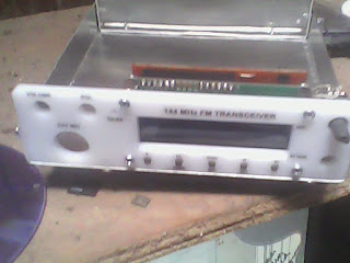
we also make the front panel with buttons below the LCD. lcd right side are the volume , squelch and mic connectors. on the left there lcd Dial Frequency and RF Gain.


 modification Icom IC - 2N with Digital Controller Atmega16A

we also designed a box for this project . The main material used aluminum, while the front panel we use acrylic material

 modification Icom IC - 2N with Digital Controller Atmega16A

 modification Icom IC - 2N with Digital Controller Atmega16A

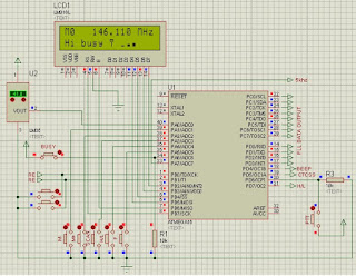
we use Proteus simulator for each of our microcontroller project . we are happy to use it because of its simplicity.


 modification Icom IC - 2N with Digital Controller Atmega16A

we use the IDE BascomAVR for modification Icom IC - 2N with Digital Control This Atmega16A.
the following new features after this project is finnished
1. Digital Dial with Rotary Encoder
2. Memory Chanel 0 - 16.
3. Signal Meter Bar
4. Auto Scan Stop
5. LCD display Informatif with TX, RX, Low/High Power, etc
6. Soft Push Button
7. 5KHz Frequency Step